4 minutes
Embedded systems programming: Part 2

This is the 2nd part of the embedded systems programming series, and in case you haven’t read the part 1 post yet, you can check it here: Embedded systems programming: Part 1
As programmers, most of you are accustomed to running your code on a standard bulky computer, but you may be wondering, if you want to build and program your own hardware gadget, let’s say a small robot car that moves around (and maybe even produce some nostalgic 8-bit beeping sound while bumping into your furniture, because why not!), then how exactly you program the car, and where exactly you place the code.
In this series, I will answer such questions, and for this post specifically, I will introduce you to the Microcontrollers.
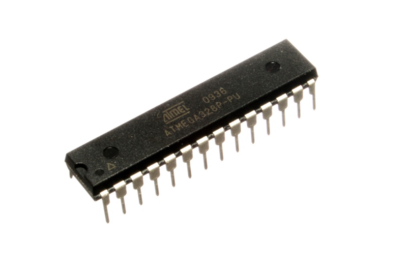
Just as we have big computers with processor(s), memory and I/O peripherals, we also have some really small computers that also have such components, and all these components are integrated inside a single chip that’s called a Microcontroller.

There is a wide range of Microcontrollers with different specs, and based on your intended usage and/or budget you can pick one that suits your needs, and they are relatively really cheap, you can get one for less than a dollar, or for a few dollars.
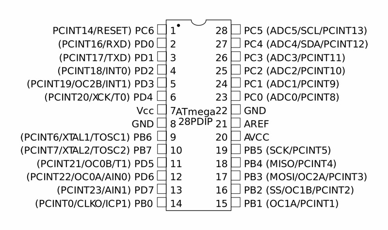
You may be wondering, how a Microcontroller interacts with its external environment, well, it does that through its pins, different pins can have different functionalities, for example they can act as input/output pins, or power pins, and certain pins can be responsible for specific communication protocols (for example SPI, I2C or CAN,…).

The Microcontroller receives input or send output as electrical signals that can be a digital high “one” or a digital low “zero”, though some pins can have analog functionalities where the voltage is more dynamic than a digital one or a digital zero.
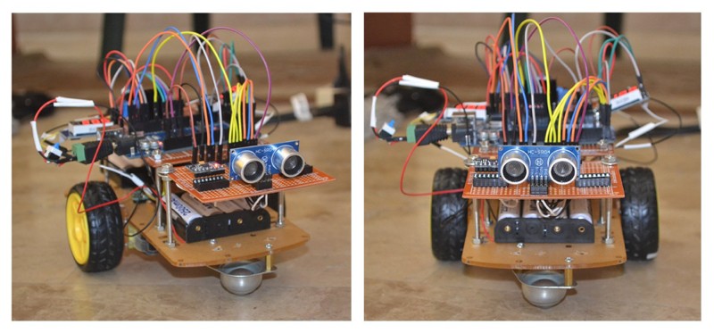
Now, let’s get back to our robot car example, let’s say we want our car to detect obstacles and automatically avoid them while moving around, what we can do is to attach an ultrasonic sensor to the car which can detect the distance between the car and the obstacle in front of the car, and then attach the sensor pins to the Microcontroller input pins (now we have an input device that sends distance data for the Microcontroller to process), and then we attach motors to the Microcontroller as well (through an intermediary hardware which is the “motor driver”, but I won’t discuss that here), and the motors will be the “output” device, so in summary, our car will get distance data from the input device which is the sensor, and based on the code that we wrote, it will take decisions accordingly and send output signals to the motors to go left or right for example and avoid the obstacle, and we can also attach a buzzer, which is a small device that do the beeping sound, and beep more intensely the closer we get to an obstacle.

We have so many devices and sensors that we can attach to microcontrollers (whether directly or indirectly) in order to receive data or to control the external world, such as temperature sensors, GPS modules, SIM cards modules, photoelectric (light) sensors, extremely precise motors, extremely powerful motors, LCD screens, and so many more, now you can start to imagine the wide range of projects that can be done by mixing these items to produce your own custom device, and don’t forget that the main part is that we can program the Microcontroller with our own code so they can do all type of crazy stuff.
And that’s it for part 2, and stay tuned for part 3.
643 Words
2021-02-21 23:24 +0200